
I wanted to make myself a mini-retina display to accompany my iMac. I discussed the solution I chose, and both the electronics and software in part 1.
Enclosure Design
For the enclosure, I considered 3D printing, but instead decided to go with a laser-cut approach. I designed the case to be produced from sheets of material, 3mm thick as this is the thickness of the LCD. Initially I considered Acrylic, but in case I made a mistake with the revision 1 design, I decided to go with MDF, as this can be easily drilled/sanded.
I then dived into to my tool of choice… Solidworks. Here’s the results:
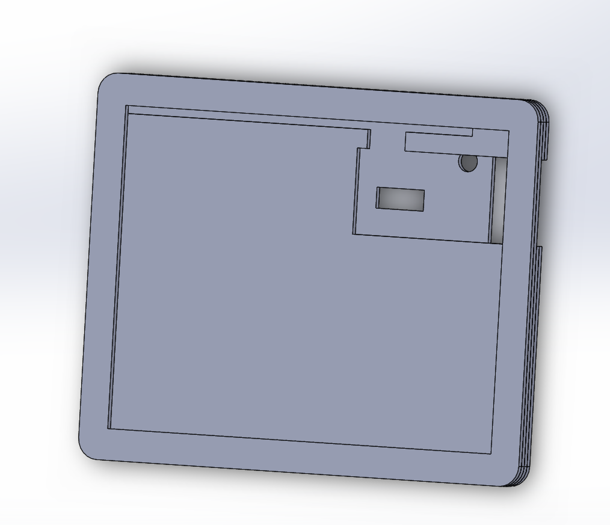
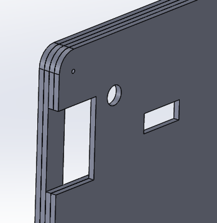

As you can see, I used 4 layers in the design:
- Front bezel – holds the LCD from the front, with a 15mm bezel around the LCD
- Mid-frame – holds the LCD around the sides, positioning it correctly for the front bezel.
- Rear Plate – holds the LCD from the back, with cutouts for the displayport adapter board
- Rear Cover – covers over the adapter board, with cutouts for components that stick out
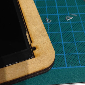
This was turned into 2D files for the laser cutter and several days later I collected my parts. The best highlight about using MDF is the roasted wood smell from the laser cutter!
I decided to cut additional plates of parts (1) and (4) out of 0.6mm polypropylene. The back plate (4) does not need to be strong, as it simply covers the adapter board which is firmly mounted to the LCD, so we can use the thin plastic sheet to reduce the z-depth of the enclosure. The front part (1) was cut to give a nice sharp finish to the case without needing paint.
The final design stack was actually 5 sheets:
- Polypropylene bezel cover – design sheet (1)
- MDF Bezel – design sheet (1)
- MDF Mid-frame – design sheet (2)
- MDF Rear Plate – design sheet (3)
- Polypropylene Rear Cover – design sheet (4)
I ended up not using the MDF rear covers.
Assembly
I ordered a new LCD (the spare was saved for repairing an iPad…) which arrived well padded in a box.

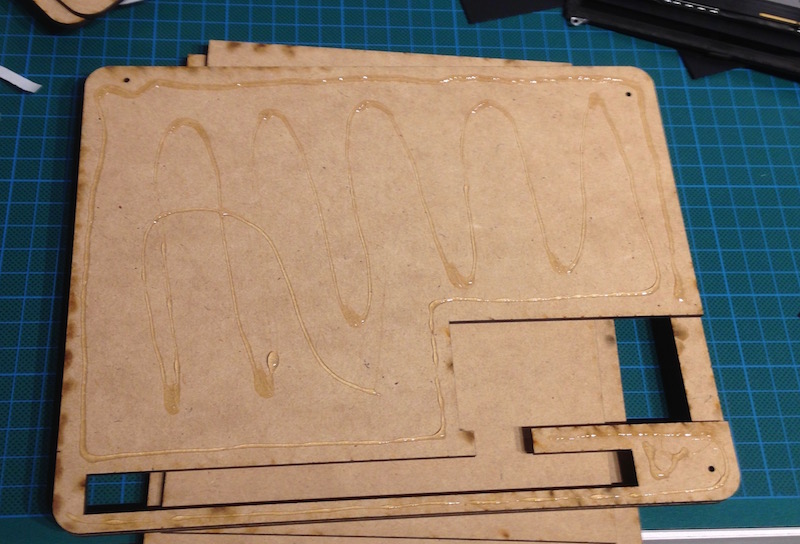
I glued the MDF layers together with craft glue, which helpfully dries very quickly, and does not dissolve the polypropylene.
I cut some scrap polypropylene offcuts to insulate the adapter board from the LCD, and used thin double sided tape to mount the adapter board to this sheet, and the sheet to the LCD.
 This double sided tape sticking the plate to the LCD backside is sufficient to prevent shearing forces on the LCD, while the back polypropylene plate provides additional mechanical support to prevent the board lifting off.
I had originally provided holes to screw the LCD into the MDF frame, but the mount points lifted the LCD above the 3mm plate height. Instead, I cut off the screw mounts so the LCD would sit flush, and then used a small amount of double sided foam on the back in a corner, to prevent the LCD from shifting around, in order to avoid putting strain on the fragile LCD cable.
I put some additional double sided foam on the board to adhere it to the back polypropylene plate (4).

I attached the back sheet (4) to the mdf part (3) using the craft glue.
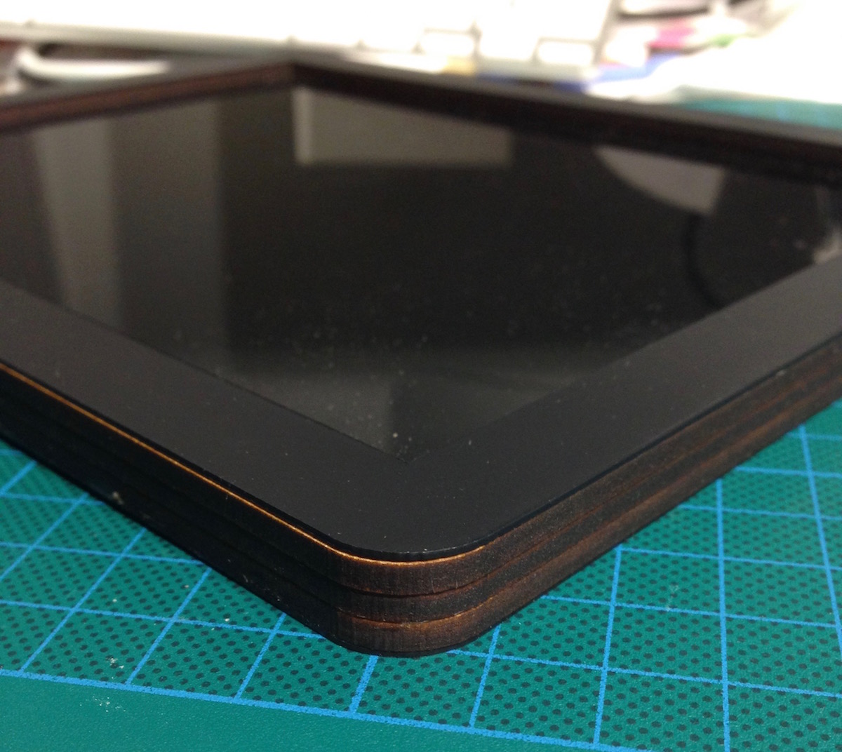
I then drilled new holes through all the MDF sheets, and found some appropriate assorted small flush-mount screws from my spare screw bin. This way I can still disassemble the screen in future if needed, as the bezel is not glued to the mid frame.
Finally, the finished product!

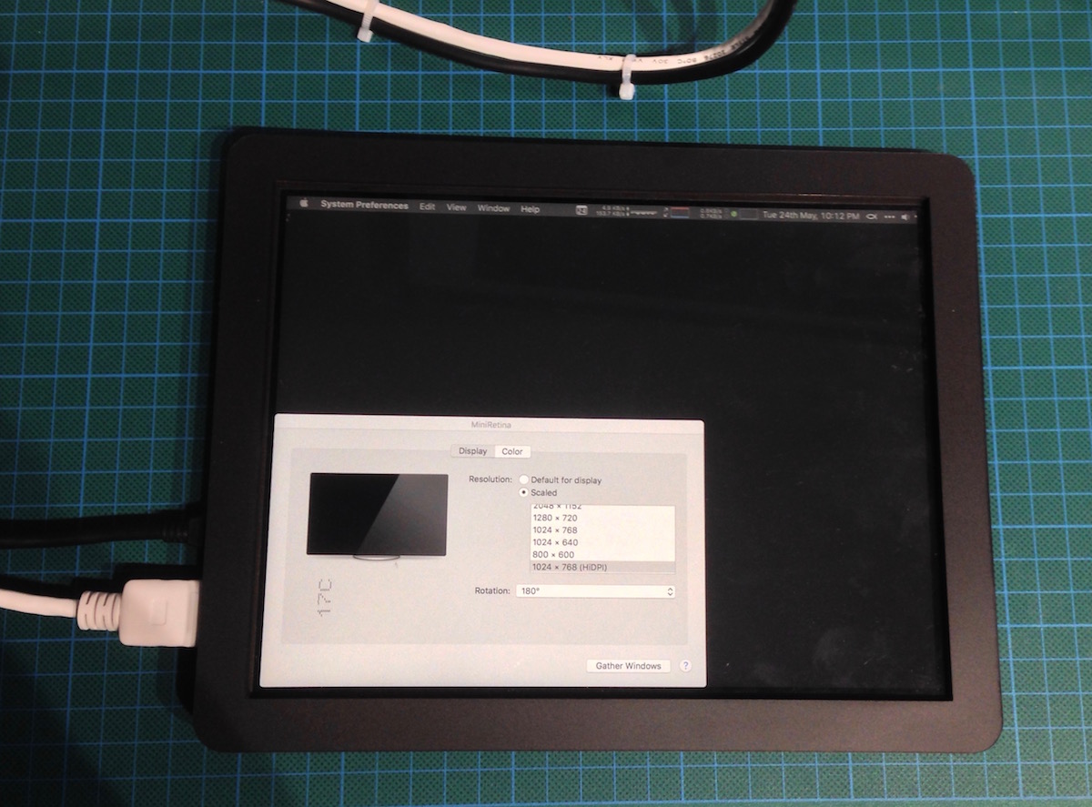
I’m now just waiting on my desk mount iPad/tablet holder to arrive!
Hello! This is really cool. Is it possible for you to share the files for this? I have a couple of the abusemark boards, and I’d like to 3d print one for myself! Looks like a fun project!
Sure! I’ll email you a link 🙂 love to see some photos if you build it! Or even if you just use it as inspiration.
Hey i just came across this and im looking for something like this to mount to the side of a small form factor pc would you mind sharing the files with me as well this looks to be one of the better models i have come across
Sure! I’ll email you now.
I couldnt thank you enough ive been in contact with a few people to know avail trying to get some type of casing put together
Hey Jonathan, how did you go with this question did you have any luck? 🙂